The Unofficial Orange Graphic Page
Last update: 11/07/2002: linked from Field Guide (GJ)
Different types of Graphic Amps
vintage
GRO 100
ORS 100
OR 80
OR 120
OR 100
OR 200
new generation
GR 80
GR 120
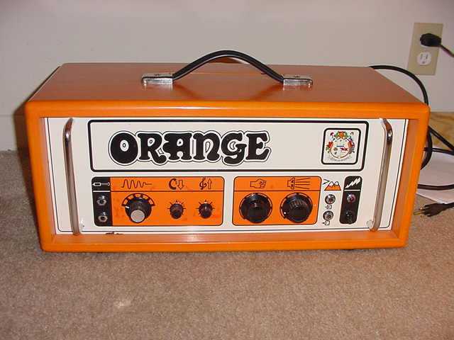
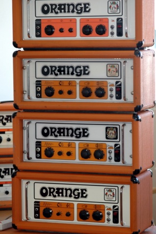
The first amps that Orange made were called "Graphic". A typical style element of these amps was the front that had only pictures to describe the controls. They also have a Frequency Analyzing Control. This is a kind of mid tone control by a six position switch.
There seems to be some confusion about which amps are GRAPHICs. I received a nice explanation on this from Christopher S. Dwyer.
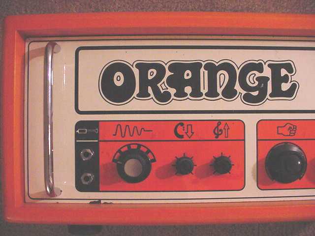
>> "Graphic" 120 and OR120 are the same thing. The "Graphic" designation came about from the ORS100 models, which had large graphics on the front with no text. The graphics depicted the knob's function, i.e. the twin mountain peaks were "Echo," the speaker was "Gain," and so on. The ORS100 models were made from about 1970 - 1972 and are the only ones to feature a plexiglas faceplate. Around 1972, the OR120 models appeared featuring smaller graphics and text on a steel faceplate. These and the lookalike "Overdrive" models are the most common Orange amps I have seen for sale. Incidentally, the ORS100 is a 100-watt amp while the OR120 is a 120-watt amp. Hope this helps.
Chris <<
Some close-up pics from an original "pics-only" ORS100 Graphic (thanks to Bart Davis):

Three different faceplates for Orange Graphics
Features
Tubes: 2 * ECC83, 2 or 4 * EL34
Controls: FAC(mid range tone control by 6 pos switch) - Bass - Treble - H.F Drive(presence) - Gain
Inputs: Bright, Normal
Outputs: 4/8/16 Ohms by Selector switch, Slave Out (kind of line out)
Features: FX loop, NO Standby switch on 70's models
Differences between versions: power plug, serial no, address of Orange company, faceplates,...
Schematics
'72 schematic
'74 schematic
post '74 schematic
There are a few differences between the three of them:
1. In the post '74 two diodes in the rectifier are drawn in the wrong direction.
2. The post '74 has a few different component values in the bass and treble controls. (c11,c12,c13)
3. The FAC components are placed the other way around in the '72 schematic.
4. The '72 schematic has 2 more resistors to bias the cathodyne phase inverter(I think...)
5. The '72 schematic has a small choke in the boost control.
6. The '72 schematic has 2k4 grid resistors instead of 2k2 in '74 and post '74 schematics.
7. The '72 schematic has a bias circuit that isn't referenced to ground????? Also seems to use another transformer that has a 72V secondary instead of a 100V secondary.